LTC SMPTE Signal Verification
Mar 3, 2026

LTC SMPTE Signal Verification
OSC See decodes LTC (Linear Timecode) for synchronization.
SMPTE
Linear Timecode
LTC is not conventional audio.
It is a data-encoded time reference transmitted as an analog waveform.
Any distortion, processing, contamination, or incorrect level can corrupt the timecode and result in:
Sync instability
Frame misreads
Time drift
Dropped lock
Complete decoding failure
For this reason, verifying the LTC waveform is mandatory before every show.
1️⃣ Correct LTC Signal Characteristics
✅ Reference – Proper LTC Waveform
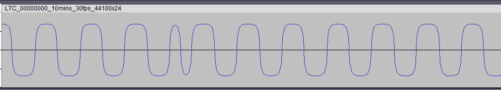
A correct LTC signal must meet the following conditions:
✔ Proper Level
Strong signal
Close to clipping
Never clipped
Recommended digital range:
Between -3 dBFS and -1 dBFS
Calibration method:
Raise the LTC level until clipping appears.
Reduce slightly until clipping disappears.
Leave the signal just below clipping threshold.
✔ Clean Waveform Structure
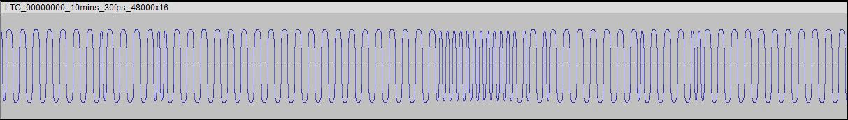
LTC is a bi-phase mark encoded square-like waveform.
It must appear:
Sharp and clearly defined
Symmetrical
Without rounded peaks
Without flattened tops
Without visible amplitude instability
If the waveform appears softened, compressed, or filtered, signal processing is occurring somewhere in the chain.
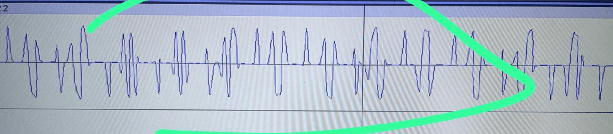
2️⃣ Incorrect LTC Signal Conditions
❌ Clipped LTC
Clipping alters bit transitions and may cause:
Frame errors
Jumping timecode
Decoder instability
❌ Low-Level LTC
If the signal is too low:
Noise floor interferes with zero crossings
Sync becomes intermittent
Decoder may drop lock
❌ Processed or Contaminated LTC
Common causes:
Master bus compression
Limiters
EQ
Analog patch bay noise
Ground loops
DI box coloration
Click track bleed
Metronome mixed into LTC channel
Additional audio routed accidentally
LTC must always be:
Dedicated channel – No processing – No summing – No effects
3️⃣ Mandatory Verification Procedure
LTC always sounds like noise.
Auditory confirmation is not sufficient.
The only reliable verification method is waveform inspection.
Recommended tools:
Audacity
Adobe Audition
Any professional DAW
Verification Steps
Route the LTC output into the computer input.
Record 10–20 seconds of incoming signal.
Zoom in at sample level.
Inspect for:
No clipping
No flat tops
No additional audio content
Stable amplitude
Clean square-like transitions
No visible noise bursts
If the waveform does not visually match the “Correct LTC” reference, the signal chain must be corrected before show operation.
4️⃣ Recommended Signal Routing for Stable Operation
For maximum reliability:
Use line-level inputs (avoid mic preamps when possible)
Avoid compressors
Avoid limiters
Avoid EQ
Avoid master bus processing
Avoid unnecessary analog stages
Keep the signal path direct and isolated
Do not share the channel with click tracks or guide audio
Best practice routing:
Playback Device (LTC Output) → Direct Line Input → OSC See Machine
This version is now technically accurate and uses only proper industry terminology.
If you’d like, I can next:
Add a troubleshooting table (Symptom → Cause → Solution)
Add a routing diagram (correct vs incorrect signal flow)
Or tighten the language further to broadcast-level documentation standards.